Telegraph Clacks out RSS Feeds
When I was a boy my father brought home from work a telegraph sounder replica kit. He was the director of the library for a local college and the sounder kit was one of several museum quality reproductions of 19th Century technology the library had acquired. The lovely brass sounder must have made a large impression, because I have wanted one for my own ever since.
Well, here at the The Workshop if you want something, you make it. I started my quest by cruising Google image search for pictures and diagrams of telegraph sounders that matched my recollections of the one my Dad brought home. As it turns out all telegraph sounders are pretty much the same so it was an easy task to collect a bunch of photos and drawing from which I could extract design details and dimensions.
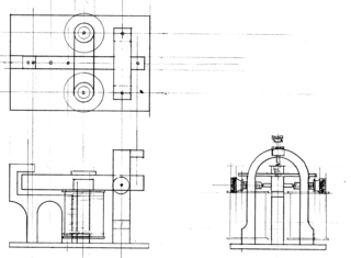
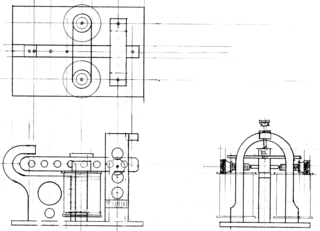
I then set out to create a scale drawing I could use to cut my materials.
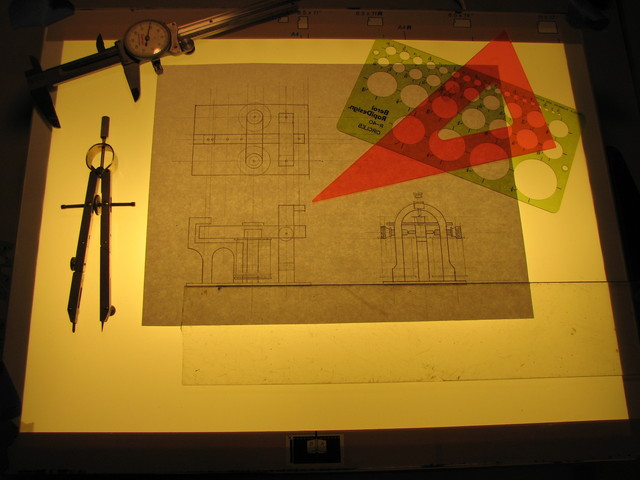
When I had my dimensions, I headed off to Metal Source to buy some brass. While I was there I noticed that they had a lot of cast aluminum sheet of various thicknesses. Remembering how nicely cast aluminum machines compared to that gooey stuff that is commonly available, I decided I'd make two sounders, a traditional replica and one for "Airship Duty."
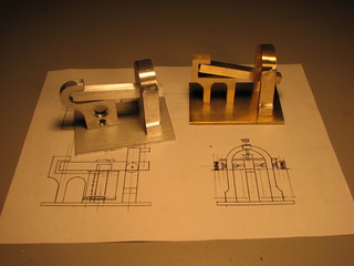
The drawing on the left is the replica which I made in brass, on the right is the lightened aluminum "Airship spec" unit. Since aluminum, and particularly cast aluminum, has different properties than brass, changes were made in the design. In particular you'll note the removal of all sharp corners as these can create stress concentrators that and lead to fatigue cracks.
Click on an image for the full size version, print this at 300 DPI if you wish to use it as a template to make your own sounder.
I scanned the drawing into the computer and printed then full size on some label stock. This allowed me to stick the label stock templates directly on to my material and make my cuts on the band saw.
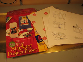

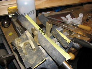
Once the rough cuts were complete I removed the majority of the saw marks with various flat, round and bastard files.
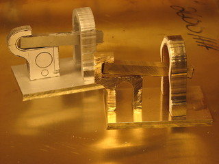
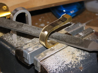
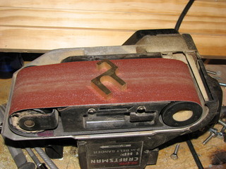
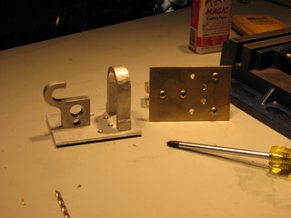
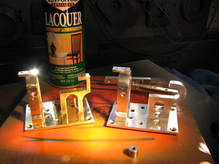
A belt sander was also very helpful in smoothing the large flat areas. Here are the sounder chassis after sanding.
To prepare the finish for the eventual polishing, I used 400 grit wet/dry sandpaper with water. The water prevents the brass and aluminum particles from clogging the paper making a single piece last a very long time.
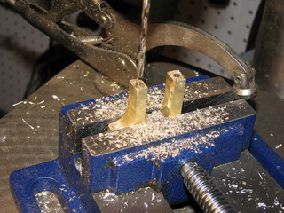
After sanding I drilled and tapped the mounting holes in the anvil and "U" shaped support.
Here's a little video tutorial on using a Tap and Die set.
Once the pieces were assembled I carefully drilled and tapped the hole for the fulcrum on my drill press.
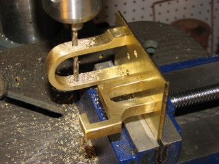
The fulcrum spindle was made from heavy gage steel wire. In fact it was one leg of a political sign from the last election. I chucked it up in my drill and used a file to machine a point on it.
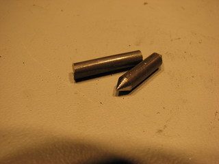
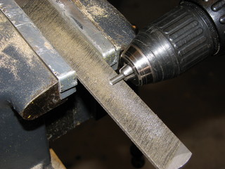
I then drilled cups in the tips of two PC case thumb screws to complete the clapper's pivot point.
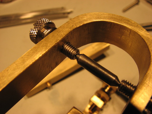
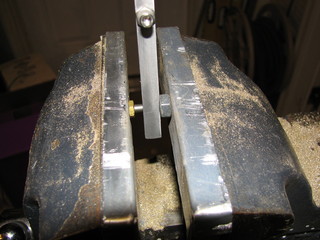
The spindle was press-fit into to a hole that was .005 of and inch too small for it using a pair of nuts.

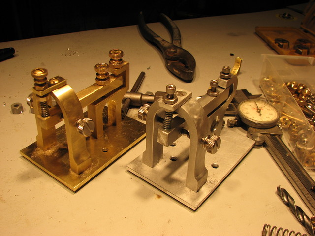
The addition of a plate at the top of the "U" support, spring, and several thumb screw adjusters completed the mechanical assemble portion of this project.
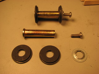
The electro-magnets were wound on a pair of cotter-less hitch pins I picked up at the hardware store. I cut the tops off just below the ring hole and the bottoms off to give them the correct height. The fiber washers and the jam nut also came from the wall of little drawers at the True Value. Finally, holes were drilled and tapped in the bottom of the pins to mount them to the plate.

Heres a tutorial on winding the coils:
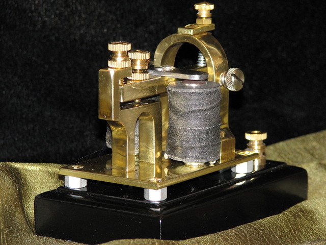
The completed brass sounders prior to polishing and mounting to there bases.
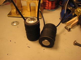
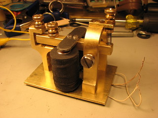
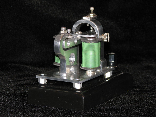
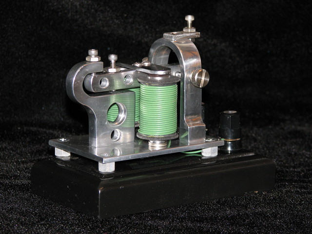
At this point the units were completely disassembled and the pieces polished with a buffing wheel and rouge. They were then re-assembled and tested. The brass unit draws about 3.5 Amps at 12 volts. I believe this is about right, historically a telegrapher sounder like this would be powered by one or two gravity cells that produce about 2 volts each. In any case, 3.5 amps at 12 volts is fine for my purposes.
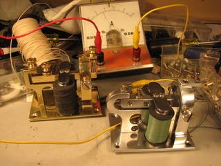
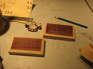
I made some simple bases for the sounders from a scrap of drawer front I picked up from the dump. Unfortunately, the piece turned out to be poplar with a cherry veneer instead of solid hardwood, so I painted them rather then using the stain I had originally intended.
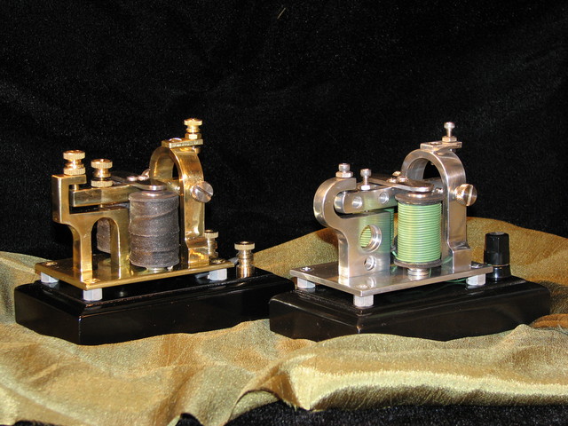
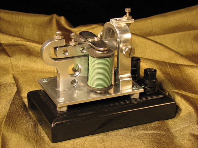
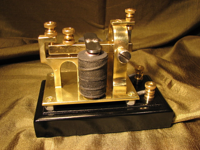
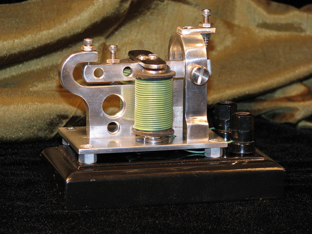
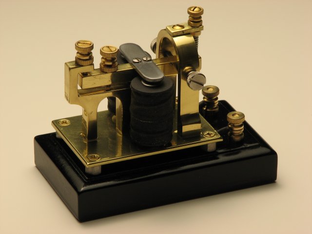
The completed sounders
Here is the brass sounder clacking out an RSS feed from Craigslist "Free" Section:
To get the sounder to tap out an RSS feed I used the Morse2LED package which is described as follows:
The morse2led package consists of two programs, blinker and text2morse. Coordinated use of the programs can translate text into morse code displayed on your keyboard's leds, as described in Neal Stephenson's Cryptonomicon.
To actually grab the RSS feed I used the well known MagpieRSS PHP script.
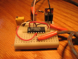
To interface the Caps Lock LED to the telegraph sounder I built a little comparator and FET driver circuit using a BUZ11 and an LM324. For prolonged use a heat sink should be added and don't forget to put a diode across the coils to shunt back-EMF away from the FET.
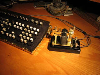
And here are the beauty shots:
Hello,I was wondering if the drawing is to scale? Ialso wonder of you have a blueprint and a list of parts
thanks John johnnyb42@verizon.net
The drawing is to scale if printed at 300DPI. I don’t have a list of parts. Note: my sounder is missing something! There should be a piece of steel or iron “connecting” the bottom of the two coils to complete the magnetic circuit. This was an oversight on my part and is the reason the sounder drew so much current.
?
WHERE DID YOU GET THE WIRE FOR THE COILS??
sorry for the upper case
Huh, for some reason your other comment and my reply aren’t showing up. I found the wire at a garage sale, I believe it’s 26 gauge but it’s not labelled. Try McMaster Carr or Newark Electronics.
thinking out loud,you said you used 12c volts.from what info i found,did they use a lower voltage on the railroad
thanks for the tip