Short Wheelbase Recumbent Bike
Collecting Materials:
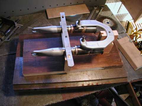
After getting my shop in order and purchasing a new drill press I began to collect the donor bikes:
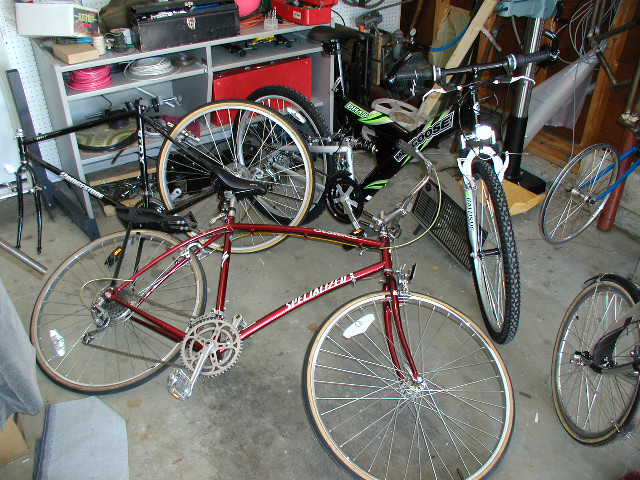
The black one is a Bridgestone that was hit by a car, it will donate the head and bottom bracket shells, handlebars and brake levels. The red bike is a Specialized Crossroads that was purchased and stripped for an Easyracer project a few years ago. The reason it looks a little weird is that it is currently fitted with the 27" running gear from my old Fuji Grand Tourer. It will donate its rear triangle. The Mongoose was just purchased and will donate the suspension components and grip shifters. It's drive train will go on an Easyracer for my wife and it's wheels and tires will be combined with some EMT tubing and an abandoned ShopLink.com container to make a beach cooler/cart.
I did attempt to purchase a frame shock and suspension fork separately, but the price of these components would have been in excess of $400 for aftermarket parts. The Mongoose parts are, admittedly, lower quality parts but for $149 they are sufficient for this experiment and if the bike turns out well I can upgrade later.
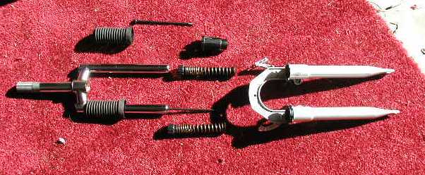
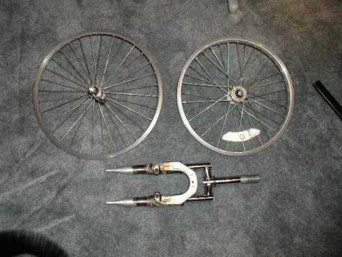
My first job will be to see if I can cut down the 26" suspension fork to fit a 20" (406mm) wheel. As you can see the fork is quite heavily constructed. It's all steel which should allow me to cut and splice the legs at will. The active components are a spring and black elastomer. The stroke is about 3" which seems kind of long for a road bike. I'm going to try and reduce that by about half.
I've decided on a 700mm x 20"(406)wheel configuration. The frame itself will be 2" by 2" 4130 Chrome-moly steel with a .065 wall. It's about twice as heavy as I wanted but I have it and I wanted to get started and I'm just not that concerned with weight. I have most of it designed in my head but I don't know what I am going to do for the seat. Right now the plan is to lay-up a fiberglass shell with a closed cell foam pad.
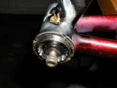
Cutting Down the Fork:
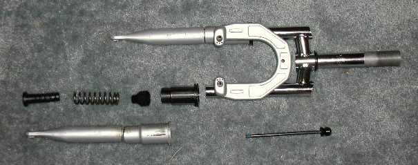
Here's the disassembled fork:
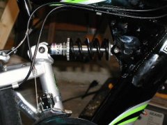
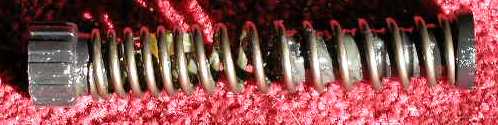
and a close up of the spring and elastomer:
Time to start cutting! I took all of the plastic guards off of my Makita power miter box and it serves quite well with a 10" metal cutting disk in place of the blade. A bit smelly and noisy though, and do were goggles.

Here's the fork after all of the cutting:
I took 1.5" out of the blades, crown and springs so it is shortened overall by 3" and the softest part of the springs is gone. I will probably need to find stiffer spring to prevent the shortened travel from causing the fork to bottom out. The bridge will also have to be welded on a bit lower for the brakes to match up with the rim.
I miscalculated the cut in the blade. It fell right where the upper spring bushing sits, this may cause the bushing to wear excessively. I should have made the cut a little higher. My original plan was to us a section of tube on the inside of the blade to splice the pieces back together but that wont be possible since the bushings are a pretty tight fit. I'll simply weld the pieces together at the cut. I hope that when I put the screws in, the bushing will end up below the cut. In any case, I will ensure that the inside of the blade is as smooth as possible with an automotive brake cylinder hone.
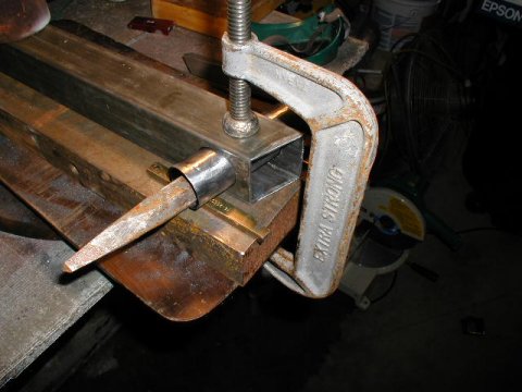
Brazing it together again:
I made a fixture to align the blades and hold the brake bridge in place. It worked for the most part but I did have to redo one of the blades. I should have had another yoke under the tops of the blade to keep then parallel. After I was done brazing I used the brake hone to ensure the the insides of the fork blade were nice and smooth.
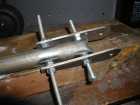
I used a hole saw to cut two washers out of a piece of 4130 flat and gas welded these to the cut off ends of the fork crown. These and the two long screws that go through them are what keep the fork from coming apart.
Here is the completed fork shown with a 411mm and a 406mm rim. The 411mm rim fits but the brake pads don't line up.
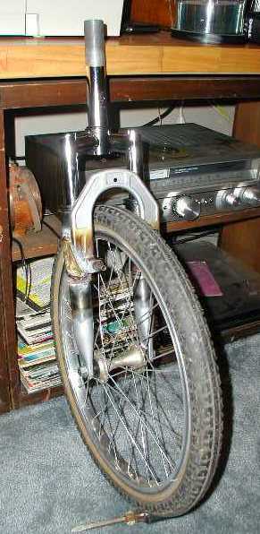
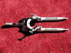
The completed assembly. I'll paint the whole bike after a thorough shakedown cruise.
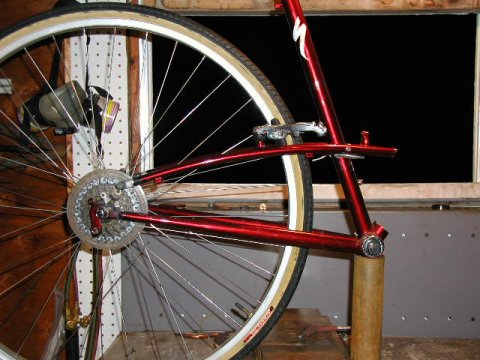
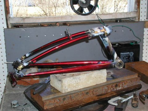
Rear Triangle
Here's the assembly fresh from the donor. The seat stays have been cut at the top and I am getting ready to un-braze them from the drop out.

With some manipulation I found a configuration where the brake braze-ons were already properly positioned. This is fortunate since the brake "braze-ons" are actually welded to the seat stays by the manufacturer..
I tacked the brake bridge to the seat tub with a bit of scrap and then cut the stays and seat tube. After cutting I carefully filed the surface to be as parallel as possible to the bottom bracket since this is where the rear shock will be mounted.
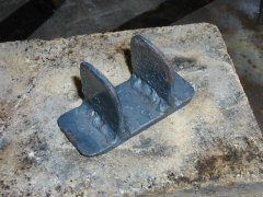
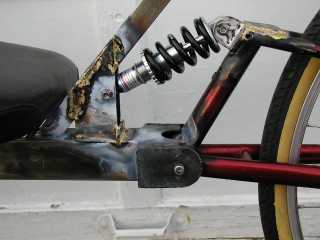
I welded up a bracket out of 4130 for the shock mount and made a jig to hold it centered and parallel. It and another top plate were brazed into place.
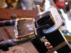
This is the completed triangle. I'll use the bottom bracket for my suspension pivot.
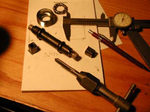
Rear Suspension
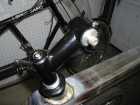
I've decided to use the bottom bracket for the rear suspension pivot. It's convenient, if a bit heavy. If the bike is a success I'm planning to mold a polyurethane bushing in place to lighten the assembly and absorb vibration.
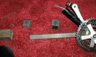
I cut the BB axle with the miter saw and then drilled and tapped the ends to accept the stainless steel Allen head bolts depicted. I'll Loctite these in place during final assembly.
Next I fabricated a mount to accept the cut down bottom bracket
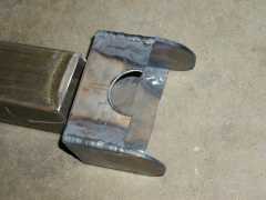
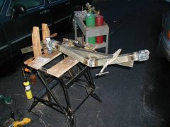
At this point I realized I needed the rest of the frame to determine the mounting points for the shock. I scaled the measurements off of the Speedmachine picture, using a vertical measurement of the back wheel diameter as my scale, and cut sections that were approximately correct in length.
Now I am going to measure the trail of the front fork and using that and my copy of Bicycling Science, determine what the head angle should be. Then I will be able to work backward from the wheelbase of the Speedmachine to determine how long my frame sections should be.
The sections shown below were all cut at 71 degrees, but the whole thing looks a bit long to me.
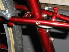
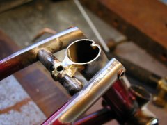
Head Tube and Assembly:
Here is the head tube jigged up for brazing. The gold shims are positioning the sleeve and the chisel is for weight to keep it from moving while I braze.
Once brazed the head tube in it was time to weld the rest of the frame together. I love the way 4130 welds with a torch! And the fumes are somewhat less irritating then brazing too.
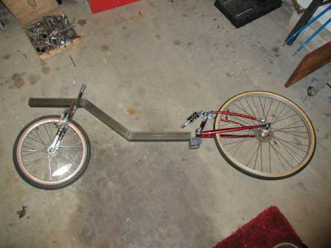
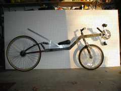
After I finished welding I put the fork and rear triangle in place and eyeballed the bike. Yes, definitely too long.
I cut about 4" out of the center section and the bike looks much better.

Once I got to this stage and I realized how complex the relationship between head angle, suspension, seat and pedals were and I changed my strategy. No matter how carefully I built this bike it was probably going to be a test bed, the real bike would be a Mark II.
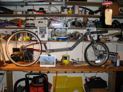
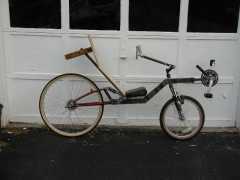
I mocked up the seat stay with 1" square aluminum so I could play with angles and shock attachment and so I could ride it for the first time to see how it would handle. Low speed handling was very good, very controllable and stable.
Head angle is 72 degrees and the fork offset is about 2 3/4". I am going to try to get the seat a bit further back so the boom will very likely be shortened from what you see here.
Seat, BB, and Handlebars:
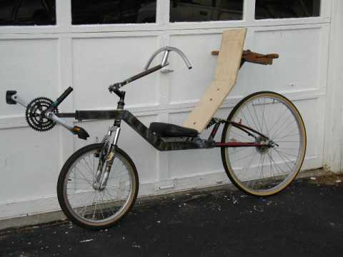
After trying several combinations of seat locations and angles I decided that the frame was still too long so I took it apart and cut 4 more inches out of the rearmost section. After that I repositioned the shock, seat and back support and brazed them in their final positions.
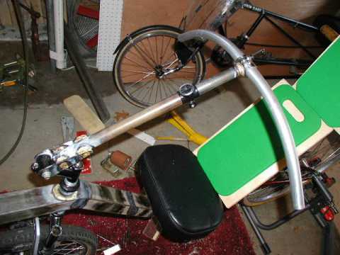
I then made some poly-carbonate blocks to located and secure the boom. I'll put a slot on the bottom of the boom and braze on a clamp.
For the handle bar I cut and taped a short length of aluminum stock to fill the stem. I fabricated a couple of plates for the hinge. The bars are designed to swing up for easy dismounts.
The black thing you see about 2/3 of the way up is the top of a second stem that I'm using as a clamp to secure the telescoping steering column. The handle bars are off of the Bridgestone and I'll probably nip a few inches off the ends.
A short ride:
Of course at this point I've gotta take it for a ride . . .
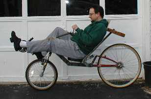
Its really quite comfortable . . .
Down the driveway . . .

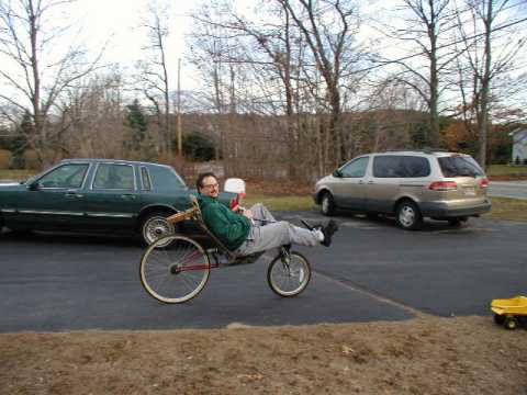
A sharp turn and back up, "Quick honey! take the picture! there's no brakes and I'm starting to roll backwards!"
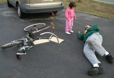
"Daddy, wha'ch you doing?"
Some More Shots:

Drive Train:
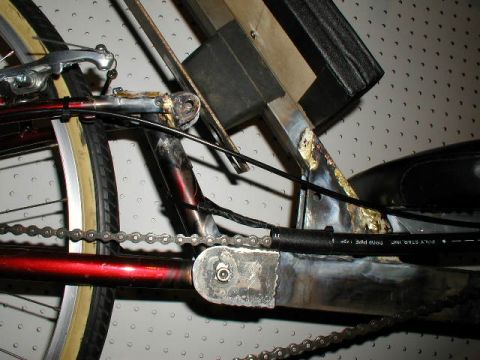
The chain line is going to be a little tricky, there are several things that make it difficult to route the chain to the back wheel. I am beginning to understand why so many people are interested in exploring front wheel drive designs.
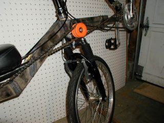
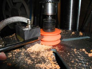
And idler is definitely needed. I'm using and old skate wheel that I notched on my drill press. I used a 5/16" bolt and some fender washers for the mandrel and the cutter is a piece of tool steel the I ground like a lathe bit.
The chain still drags on the bottom of the seat sometimes so I installed a chain tube of irrigation pipe. I do plan to fix this interference but not until I finalize the rear suspension. The few quick rides I've taken so far have convinced me that the mountain bike shock isn't going to work, it's too big and has too much travel.
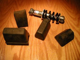
I am going to make a new rear shock with some sort of elastomer. These are car and truck suspension limiters. I drove my wife crazy the other day by making her stop the mini-van every time I saw one lying by the side of the road!