Jump to Navigation

Telegraph Clacks out RSS Feeds

When I was a boy my father brought home from work a telegraph sounder replica kit.  He was the director of the library for a local college and the sounder kit was one of several museum quality reproductions of 19th Century technology the library had acquired.  The lovely brass sounder must have made a large impression, because I have wanted one for my own ever since.

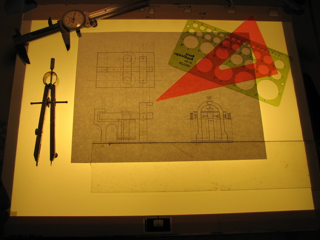
Well, here at the The Workshop if you want something, you make it.  I started my quest by cruising Google image search for pictures and diagrams of telegraph sounders that matched my recollections of the one my Dad brought home.  As it turns out all telegraph sounders are pretty much the same so it was an easy task to collect a bunch of photos and drawing from which I could extract design details and dimensions.

I then set out to create a scale drawing I could use to cut my materials.

telegraph design

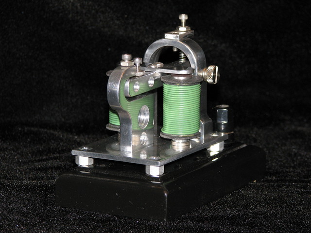
When I had my dimensions, I headed off to Metal Source to buy some brass.  While I was there I noticed that they had a lot of cast aluminum sheet of various thicknesses.  Remembering how nicely cast aluminum machines compared to that gooey stuff that is commonly available, I decided I'd make two sounders, a traditional replica and one for "Airship Duty."

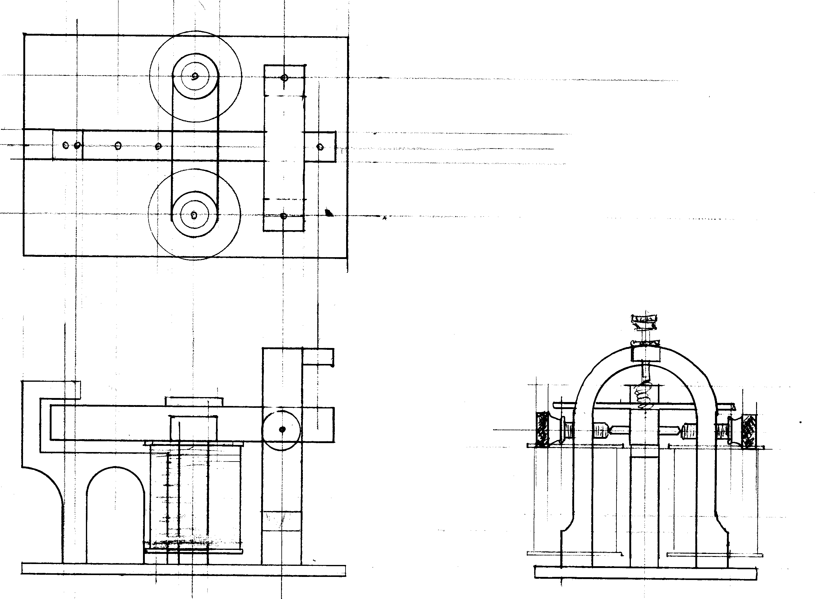
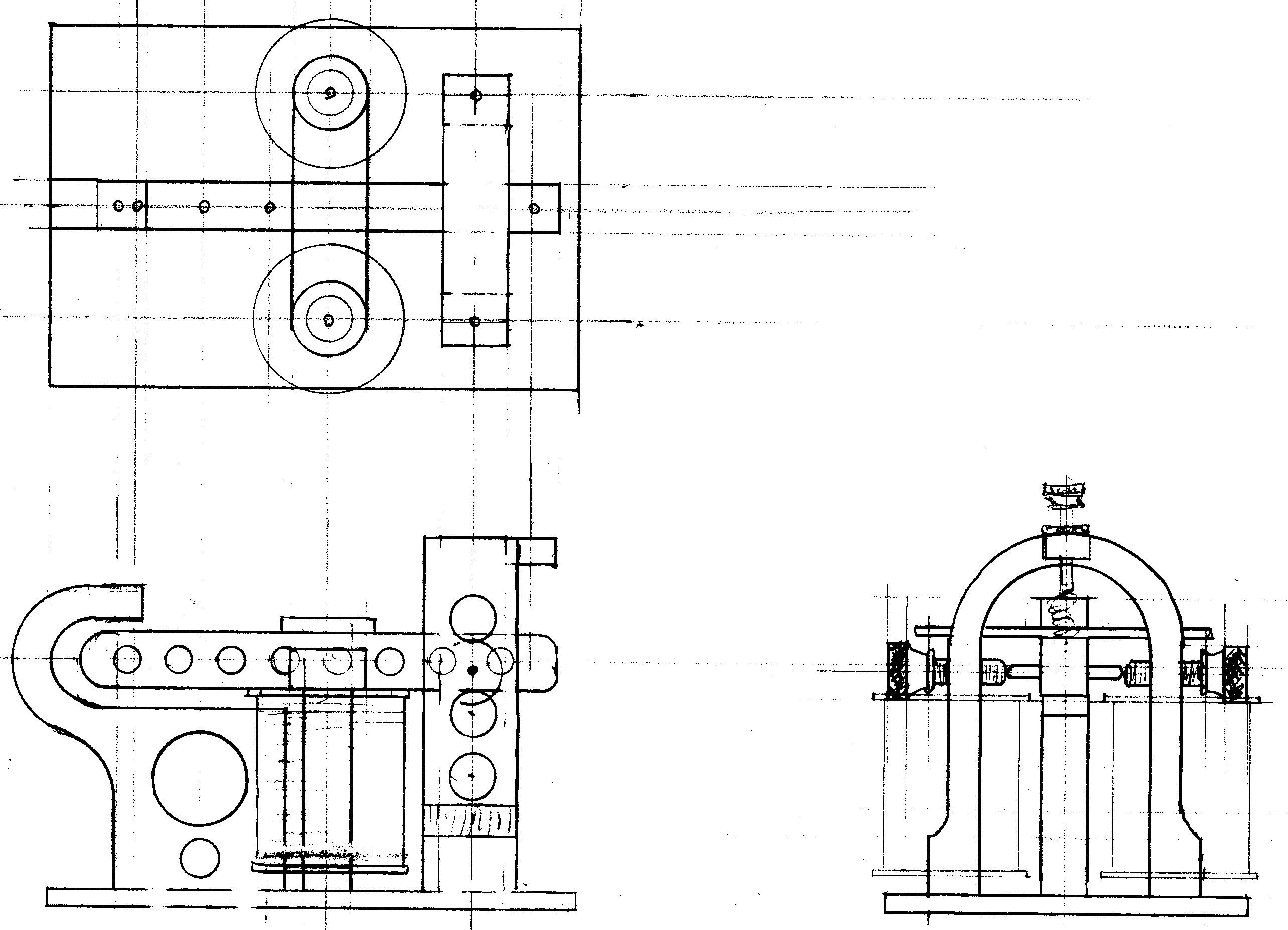
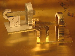
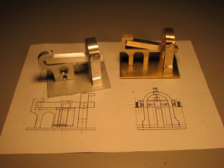
The drawing on the left is the replica which I made in brass, on the right is the lightened aluminum "Airship spec" unit.  Since aluminum, and particularly cast aluminum, has different properties than brass, changes were made in the design.  In particular you'll note the removal of all sharp corners as these can create stress concentrators that and lead to fatigue cracks.

Click on an image for the full size version, print this at 300 DPI if you wish to use it as a template to make your own sounder.

brass telegraphairship telegraph

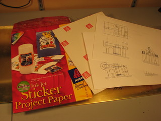
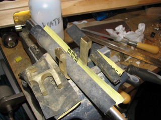
I scanned the drawing into the computer and printed then full size on some label stock.  This allowed me to stick the label stock templates directly on to my material and make my cuts on the band saw.

sticker template  bandsaw brass cutting

Once the rough cuts were complete I removed the majority of the saw marks with various flat, round and bastard files.

aluminum and brass cut on bandsaw  file brass smooth

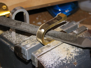
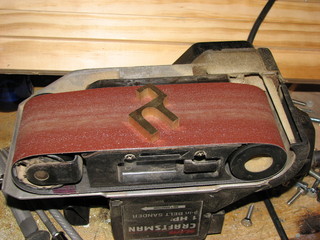
A belt sander was also very helpful in smoothing the large flat areas.  Here are the sounder chassis after sanding.

brass on belt sander  semi-finished telegraph sounders

To prepare the finish for the eventual polishing, I used 400 grit wet/dry sandpaper with water.  The water prevents the brass and aluminum particles from clogging the paper making a single piece last a very long time.

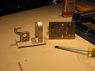
After sanding I drilled and tapped the mounting holes in the anvil and "U" shaped support.

brass sanding with buck  drill mounting holes

Here's a little video tutorial on using a Tap and Die set.

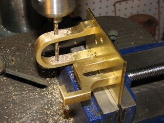
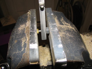
Once the pieces were assembled I carefully drilled and tapped the hole for the fulcrum on my drill press.

screm aluminum together  drill pivot holes

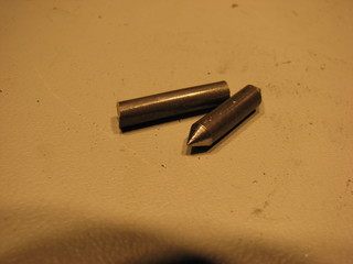
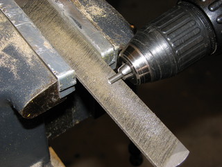
The fulcrum spindle was made from heavy gage steel wire.  In fact it was one leg of a political sign from the last election.  I chucked it up in my drill and used a file to machine a point on it.

pivot axle  drill pointing

I then drilled cups in the tips of two PC case thumb screws to complete the clapper's pivot point.

fulcrum

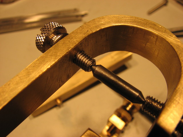
The spindle was press-fit into to a hole that was .005 of and inch too small for it using a pair of nuts.

press fit axle  armature and pivot

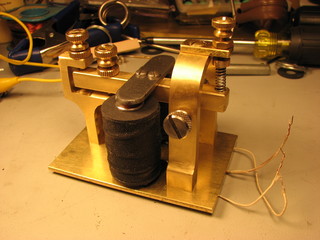
The addition of a plate at the top of the "U" support, spring, and several thumb screw adjusters completed the mechanical assemble portion of this project.

telegraph assemblies and caliper

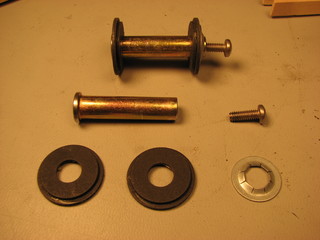
The electro-magnets were wound on a pair of cotter-less hitch pins I picked up at the hardware store.  I cut the tops off just below the ring hole and the bottoms off to give them the correct height.  The fiber washers and the jam nut also came from the wall of little drawers at the True Value.  Finally, holes were drilled and tapped in the bottom of the pins to mount them to the plate.

linch pins and hitch pins  magnet coil forms

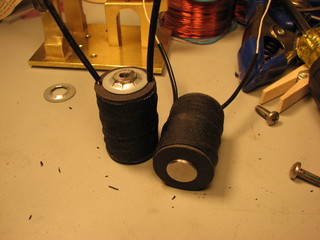
Heres a tutorial on winding the coils:

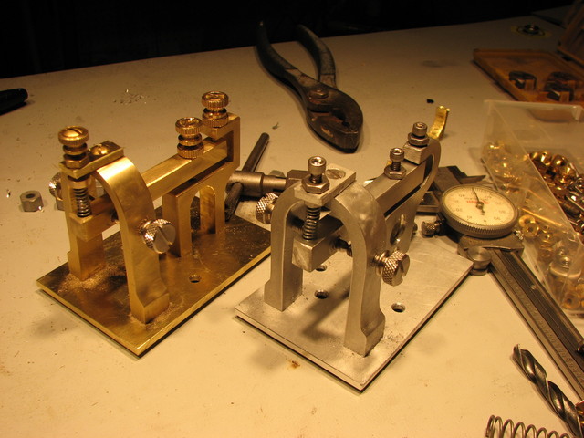
The completed brass sounders prior to polishing and mounting to there bases.

electro magnets  sounder assemblied

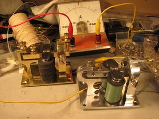
At this point the units were completely disassembled and the pieces polished with a buffing wheel and rouge.  They were then re-assembled and tested.  The brass unit draws about 3.5 Amps at 12 volts.  I believe this is about right, historically a telegrapher sounder like this would be powered by one or two gravity cells that produce about 2 volts each.  In any case, 3.5 amps at 12 volts is fine for my purposes.

lacquer sounder  coil amperage test

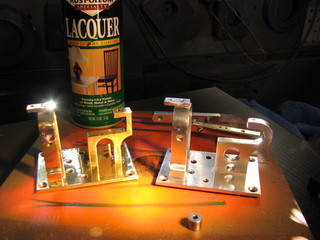
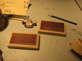
I made some simple bases for the sounders from a scrap of drawer front I picked up from the dump.  Unfortunately, the piece turned out to be poplar with a cherry veneer instead of solid hardwood, so I painted them rather then using the stain I had originally intended.

wood bases for telegraph sounder

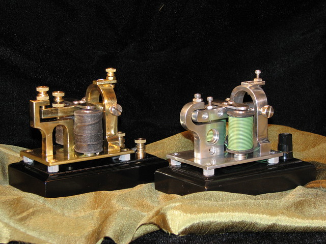
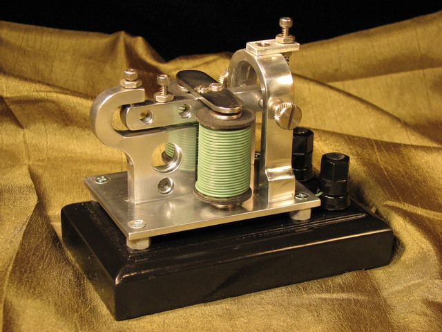
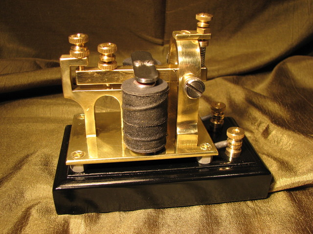
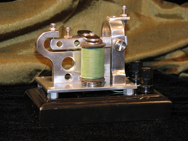
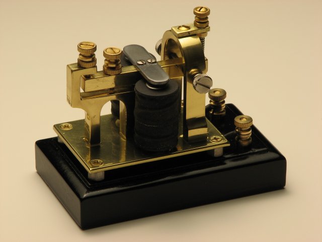
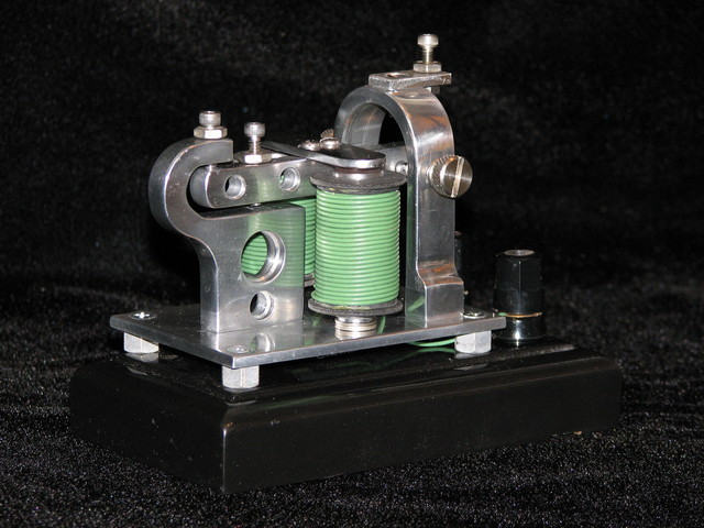
The completed sounders

sexy sounders

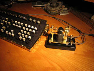
Here is the brass sounder clacking out an RSS feed from Craigslist "Free" Section:

To get the sounder to tap out an RSS feed I used the Morse2LED package which is described as follows:

The morse2led package consists of two programs, blinker and text2morse. Coordinated use of the programs can translate text into morse code displayed on your keyboard's leds, as described in Neal Stephenson's Cryptonomicon.

To actually grab the RSS feed I used the well known MagpieRSS PHP script.

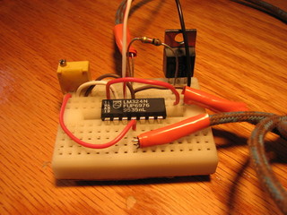
To interface the Caps Lock LED to the telegraph sounder I built a little comparator and FET driver circuit using a BUZ11 and an LM324.  For prolonged use a heat sink should be added and don't forget to put a diode across the coils to shunt back-EMF away from the FET.

telegraph and steampunk keyboard  LM324 circuit

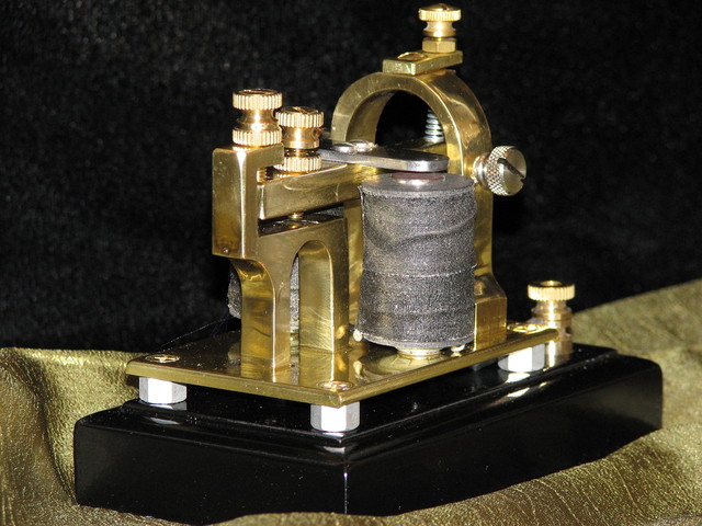
And here are the beauty shots:

sounder for airship duty

nice brass

nice aluminum

oh baby

sweet

airship hotness

brassy

Comments

It's extremely hard to build all that by ourselves.

I suggest to make videos that show building the Telegraph step by step .

-.-- --- ..- .-. / -- --- .-. ... . / -.-. --- -.. . / - .- .--. .--. . .-. / .-.. --- --- -.- ... / ... ..- .--. . .-. .--. --..-- / .-.. .. -.- . / .. - ... / -... .-. .- -. -.. / -. . .-- / -... ..- - / .. - .----. ... / .---- ----- ----- / -.-- . .- .-. ... / .- --. --- .-.-.- / .. / .-.. --- ...- . / -.-- --- ..- .-. / ... - ..- ..-. ..-. .-.-.-

- .... .- -. -.- / -.-- --- ..- / ..-. --- .-. / - .... . / -.- .. -. -.. / .-- --- .-. -.. ... .-.-.- / -.-. .... . . .-. ... .-.-.- / .--- .- -.- . .-.-.-

-- -.-- .--. .-.. . .- ... ..- .-. . .-.-.- - .... .. ... - .... .. -. --. .-. . .- .-.. .-.. -.-- .-- --- .-. -.- ... ... .-.. --- .-- .... --- ... - --- ..- -

-.. .. -.. / -.-- --- ..- / -.- -. --- .-- / -.-- --- ..- / -.-. .- -. / .--- ..- ... - / ..-. .. -. . / -- --- .-. ... . / -.-. --- -.. . / - .-. .- -. ... .-.. .- - --- .-. ... / --- -. .-.. .. -. . ..--.. / .. / -.. .. -.. -. .----. - .-.-.- / .... - - .--. ---... -..-. -..-. -- --- .-. ... . -.-. --- -.. . .-.-.- ... -.-. .--. .... .. .-.. .-.. .. .--. ... .-.-.- -.-. --- -- -..-. .--- - .-. .- -. ... .-.. .- - --- .-. .-.-.- .... - -- .-..

This is awesome!!! I didn't even know a band saw could cut metal! Now, when you say you interfaced the Capslock LED to the other dealy-doo, what you're doing is you're having the caps lock button's LED light up in sync with the RSS feed being tapped out? I wasn't sure, but if I'm understanding it correctly, that's a nice touch!

Well done!

Like you, as a boy of 12 I was interested in the old railroad style telegraph keys and sounders. I do not remember how, but I managed to obtain two such devices mfg around 1908 to 1912 to learn morse code so I could qualify for an FCC novice license. As a kid I always had a strong interest in how and why things worked. This was in Baltimore, MD. I eventually became an electronics engineer and wound up in San Diego.

I brought those telegraph instruments with me and they have been stored in boxes all these years. I retired several years ago and now have time to pursue some hobbies again. I first saw your SteamPunk work in the IEEE Spectrum magazine one or two months ago. Your work with the telegraph sounder operated by an RSS feed inspired me to polish up my old Telegraph sounder and design an interface to operate the sounder from an MP3 player.

When I show it to my children and grandchildren I didn't want to be tied to the computer. I found transcripts of the Titantic distress calls and after creating a text file I used a text-to-morse converter from the internet to create 800 Hz morse code files and save them as MP3 files. I then designed and built a tone-to-pulse converter that would take the MP3 files from and MP3 player and drive the telegraph sounder.

On cleaning up the Telegraph instruments I found engraved on the sounder arms the name Manhatten Elec Supply Co. A Google search turned up old catalog pages with these telegraph instruments listed. Telegraph History

This is how I was able to pin the date of mfg to between 1908 and 1912.

I would like to pass on to you photos of my "Improved Giant Sounder" and "Eureka Telegraph Instrument" from the turn of the last century, schematic diagram of the tone to sounder converter, and a little videos of clacking out the Titantic distress calls.
Here is a link to where you may find the images and videos posted - JH Trageser Images

Until the IEEE spectrum feature article I had not heard of the SteamPunk movement. Now you have me interested. I was also interested as a kid in the model steam engines. I eventually obtained a model Stirling engine in 1977. I just resurrected it to use to drive a Lionel metal Ferris Wheel circa 1940's, that my Dad had with his Standard Gauge train layout.

Jim Trageser

Oh how cool! Thank you for your comments and the links! Marvelous!

Jake.

Hello,
extra nice work, I like it because I use Morse code. Wish you good work in the future, best greetings!

Your Craftsmanship and Photographic skills never cease to impress me when I visit this site.

Jim

 LOL! and this is before I learned what "white balance" was!  
Thanks for the kind words!

Thanks for this great article, it's exactly what I need!

I'd like to try following your instructions and build one of my own. It looks pretty straightforward, but do you have an exact materials list you could share? I can probably figure most of it out but it's always better if you know you have the right parts before starting ...

In the printout, the dimensions came out to 3 1/2 " x 2 3/8 " - is that correct? want to make sure the printer's not scaling the image wrong or anything.

Yes, those are the right dimensions.  There is no exact parts list, I used what I had lying around - most of it you should be able to find in the little drawers at the hardware store.

Hi Jake!
Love the sounders!
Your current draw sounds high to me. If you use a smaller gage wire, it should be less, but have better action. Some cotton or silk covered 30 gage would be perfect, but hard to find.

3's om e gl

It is high, but what's missing in my design is a piece of iron across the bottom of the two electromagnets to complete the magnetic circuit.  Someday I'll get around to fixing that.

Yes, completing the magnetic circuit is a plus, but what is really missing is the chamfer box and candelabra base.
The base raises the sounder closer to the ear, and the box directs the sound to the ear.
We older ops need all the help we can get in the hearing department...

Cool... awesome winding video... I've been looking for that info for ages...
How did you do the embedded videos with amazon links?
I can't seem to find that widget in my associate account...

Thanks...
:)

 Thanks! the vids are from an old program, they're maintaining existing vids but no longer allowing creation of new vids.

...sorta -- I copied the code from the video (with the help of Audacity) and it doesn't look much like craigslist but rather:

tfreeviweoiporfreeipownanoiminurfeewztappingouturmorse

OK, maybe I got some of those wrong.

Looks to be about a 20 wpm rate.

I came across this page via google, as I'm currently working on a project with the aim of working a telegraph sounder with an arduino. The sounder is much like the one you replicated, except an original item (Western Electric http://bit.ly/522B7g). The arduino drives a biploar transistor to switch the current on and off. Like you say, a diode is in order to clip the otherwise large voltage spikes across the coil.

One thing though: it worked fine up to around 20 wpm, but the stories of yore tell of operators who could work 40 wpm or even more, & I just couldn't get the sounder to work that fast. Bottom line is that the coil just doesn't demagnetize very fast through the diode, so to improve the situation I put a diode in series with a 50 ohm resistor across the coil. the action becomes much snappier & approaching 40 wpm is possible. The voltage across the cutoff transistor stays reasonable with this arrangement.

Amazing reproduction!

 Haha! You're the first to actually decode the Morse!  At the time this page was published Craigslist/free was FILLED with fake offers for "free video ipod" and the last part is, of course, Lolcat speak: "Im in ur feedz tapping out ur morse."
Bravo!
That's fascinating, I hadn't though of it but of course the diode would have an effect - you've also probably noted the glaring error in the design of my sounder, the failure to complete the magnetic path due to the use of a brass base rather than a steel one or the inclusion of an iron bar across the bottom of the coils. I expect that my current draw will be far more reasonable when I fix that.
 

Well, I guess either your code or I had some problems with the d's!

The WE sounder I have does have an iron bar at the top and bottom of the coils, completing the magnetic circuit. The coil resistance is about 30 ohms, quite a bit higher than what yours reads. It works on about 100mA.

The question is whether the original poster was using continental code which later was adopted as the International Radio Telegraph Code or are they using genuine Morse. Morse Code was only used on North American Land line telegraph circuits. There are short spaces in some of the Morse characters. Morse code was devised to be read visually and came to be read by ear when the operators found they could copy more quickly by listening to the clicking of the relays which controlled the pen and ink registers than they could by reading the dots and dashes on the paper tape. Those marks on the paper tape were the origin of the terms dot and dash. Morse had been a teacher for the deaf and he may have hoped that his telegraph could provide a source of employment for them. The fact that higher speeds could be achieved when reading by ear doomed that idea before it even began. Pen and ink registers were mechanically elaborate devices that needed a lot of maintenance so they were rapidly displaced by sounders once that was discovered to be a simpler and quicker receiving instrument. Adoption of sounders in place of pen and ink registers was resisted at first by the perceived need for a permanent record of the signal as received. Once it was realized that the tape could readily be produced locally the value of such a record was negated and adoption of sounder only receiving proceeded quickly. Box relays were developed to allow the relay station operators to listen for their station ID on the circuit when they had set the station to relay the signal without local operator intervention. Resonators were developed to make the sounders as loud as a box relay.
--
TAtkinsH

http://www.youtube.com/watch?v=oo0hSZ9R_Xk

Alfred was a mechanical genius, I thought you would appreciate this information, I have invented a clean energy device based on another of his not known experiments, I'm married to one of his descendants. Funny thing I want to adapt it to this brilliant "steam punk" style.
Best Regards.

do you know where i could purchase one of these, i dont have the tools