Putting an Angle Lamp Back in Oil
One of the tragic realities of Angle Lamps is that many have been electrified in a crude and destructive manner. Below is such a lamp. I bought this lamp on eBay thinking that it was solid brass. I intended to move the burners from a tin plate Angle Lamp over to this body. However, when it arrived I discovered that it was tin plate also and, in fact, had only a brass wash that had been destroyed inan attempt to polish the lamp. All in all a pretty sad case.
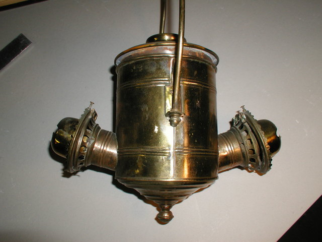
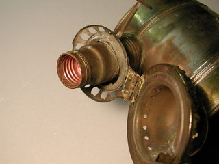
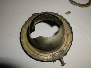
Typically an "electrocution" will start with the removal of the wick tube and the gutting of the burner assembly to provide space for the Edison socket. A hole for the base of the light bulb will be drilled or cut with snips in the burner shell.
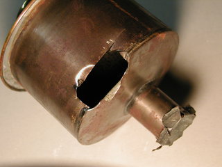
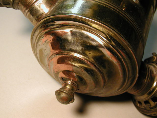
In addition, the kerosene tank will often be cut or drilled to provide clearance for the wires. You can see what a lovely job the some unknown "craftsman" didwith my lamp.
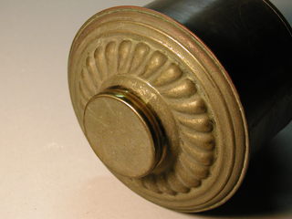
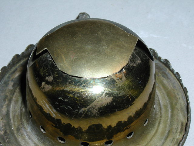
The top of the kerosene tank is actually in very nice shape. The varnish, although oxidized, has protected the brass. The base, however, has been polished and several layers of finish and sub-finish have been removed and exposed.
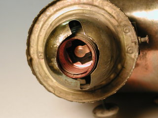
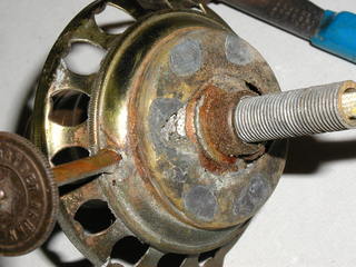
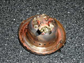
Here you can see that the screens are gone, the plate that holds the wick tube has been cut out and the bottom of the burner has been drilled and has had several holes punched it it. The wick adjusting knob has been cut off and soldered in it's hole.
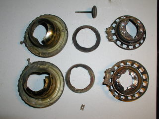
Here are the parts of the disassembled burner, at bottom you can see a bit of one of the cogs that raise and lower the wick. From this I should be able to figure out the proper shape so I cancut a new cog.
I'm going to start with the burner shell as it looks like the hardest part to fix. I first cut a small square of brass that I placed over the ball-peen of a hammer set in my vice and struck with a rubber mallet. Repeated blows shaped the brass until the dome formed matched that of the burner shell quite nicely.
I then cut out a piece of brass the fit the hole in the burner as closely as possible and tried to silver solder it in place with my oxy-acetylene torch.
The silver solder didn't work very well, I suspect that I need a different flux as I could not get the solder to adhere well to the base metal. However, I did have pretty good luck with low fuming bronze brazing rod. In several places I melted through the thinner brass patch but was able to fill the holes with material from the brazing rod.
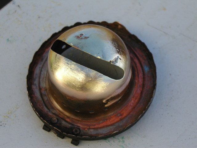
As you can see below I made a bit of a mess. I was kind of disappointed that the silver solder didn't work and frankly I wasn't too enthused with the result of my experiment. However, once I removed the excess bronze with a sanding drum on a Dremel tool the result was not half bad.
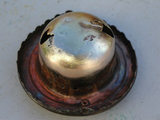
I did some further clean up with a wire brush and cut out the slot with a cutting disk on the Dremel and I found I had a serviceable part. With a little more material added here and there and some more finish work I'm confident that I can make a respectable repair.
The second burner shell should be easier too, the lessons learned with this experiment are:
- use a thinner brazing rod, 1/8" doesn't give enough control
- use a brass patch that is closer to the thickness of the base metal, mine was about 2/3 the thickness of the shell and I melted several holes in it that had to be filled.
Stay tuned – as soon as I get the thinner rod and thicker stock I'll be brazing the other shell. After that I'll need to:
- Find replacement for the screens
- Fabricate the wick tube
- reconstruct the adjuster mechanism
- reassemble the burner
- repair or rebuild the tank
- reassemble and finish the body.